
Project:
ecgc
Date:
12/06/2023
(Provisional) end to audio research
Hello there again, I'm back after a long semester. I bring updates on the audio controller, which I've worked on the last 4 months. I don't want to keep apologising for every long silence, so I'll just keep going.
Current audio prototype
As discussed in the previous post, I have been working on an audio controller for the cartridge. It was a low-priority goal I set early on in the project, but worked on it for a school project.
The current prototype consists of 2 parts: audio controller firmware and supporting hardware. The firmware syntheses the correct waveforms based on its configuration, and the hardware is used to convert the controller's output to a sound wave suitable for the Gameboy's specs.
The current capabilities are slim, but form a strong foundation:
- The controller can synthesise any waveform consisting of 256 8-bit samples.
- The waveform buffer can output its buffer anywhere from ~50Hz to ~50kHz.
- The waveform is volume controlled with 16 volume levels (one of them being muted).
- The controller can output 4 independent audio channels, each with the capabilities listed above
Audio controller firmware
Overview
I've provided a high-level block diagram of the controller's firmware below. It shows the main audio controller being connected to the Wishbone bus, making it accessible as a memory-mapped peripheral in the cartridge's memory map. It has a couple of registers for controlling runtime behaviour for stuff like frequency and volume control.
The main audio controller keeps 4 audio voices, which it can control with a simple configuration interface. The audio voice is the more complex part, but I'll focus on it a bit later.
The output of each voice is then outputted on IO pins on the FPGA, but I'll discuss the hardware later.

Sample table and clock
That's it for the short overview, now let's look more in depth to the audio voices. I've provided a block diagram below to help explain its inner workings.

The heart of the audio voice is the sample table with its sample clock. At each clock edge, the next sample is put on its output. The sample clock is set by its 11-bit pre-scaler, which can divide a 30.1MHz clock by a factor of 211, which makes a ~14.7kHz clock. This is in samples per second, but if we take into account the number of samples and say that one buffer contains an entire wave cycle, we divide the frequency again by 256 samples. This gives us a frequency range from ~117.58kHz to ~57.4Hz.
One might look at the highest frequency and wonder why it's 6 times the maximum of human hearing? The reason for this is the reduced resolution of the pre-scaler at high frequencies. If we compare the difference between a pre-scaler values 2 and 3 and the difference between 1002 and 1003, the reason becomes apparent.
Going from a value of 2 to 3 lowers the wave frequency by ~9.8kHz, while going from 1002 to 1003 lowers it by just ~116.8Hz. Now these extreme jumps happen well beyond human hearing and increasing the maximum frequency gives us better resolution in the range were it matters. I wrote a script to calculate the pre-scaler values by a given frequency and gave it a table of note frequencies. Due to the integer nature of the pre-scaler, there will always be a slight error but the largest error that I found was a deviation of 2%. So pretty good, if I do say so myself. But I might decrease the 30.1MHz clock in the future to get lower notes.
PWM modulation
The audio signal is outputted as a modulated PWM signal. The duty cycle of the PWM signal corresponds to the analogue voltage level of the audio. With a fast enough PWM signal, one can recreate the original audio signal with proper filtering. A big benefit of having a PWM signal, is that this is a digital signal. The FPGA I have does not have analogue capabilities, meaning it can only output digital signals. Outputting a digital PWM signal allows me to save money and PCB real estate on expensive DAC components.
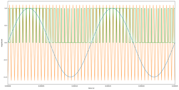
In any case, the PWM signal is modulated using the audio samples and a triangle counter. By comparing the 2 values and setting the pin high when the audio sample is larger then the counter value, one can combine the 2 signals. Graphically, it looks like the graph below. Here the blue line is the audio, the orange line is the triangle counter, and the green line is the modulated PWM signal.
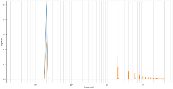
Now this might look weird, but I swear that the green PWM signal contains our audio. If we do a frequency analysis (see image below), we can see that the original 2kHz sine is present in the PWM signal. There also is some high frequency components which originate from the triangle wave, but this can be electronically filtered out, which I'll discuss later.
Volume control
Looking at figure 2, one might see 2 lines labelled "volume control" coming from the control logic. There are 2 types of control logic implemented in the audio voice, one for coarse (bit shifting) and one for fine control (counter ceiling increase). The volume control is configured by use of a 4-bit register, where each value corresponds to a volume level. There are 2 groups: the lower 2 bits control the triangle counter; and the upper 2 bits control the bit shifting. The infographic below shows what each group does when their bits are set to the value on the left.
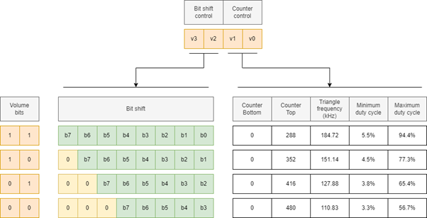
The bit shift bits have 4 settings, each shifting bits further to the right. This loses a bit of audio data in each subsequent setting, but is able to reduce the volume 8 times. Each bit shift halves the volume amplitude.
The counter also has 4 settings. Each setting increases the triangle counter ceiling by 64, reducing the PWM frequency and maximum duty cycle. The reduction on the maximum duty cycle results in volume reduction, but only being limited to reducing the volume close to 50%.
Hardware
I also developed hardware for the research. I developed 2 different prototypes: one was for researching filtering and the other was for researching mixing.
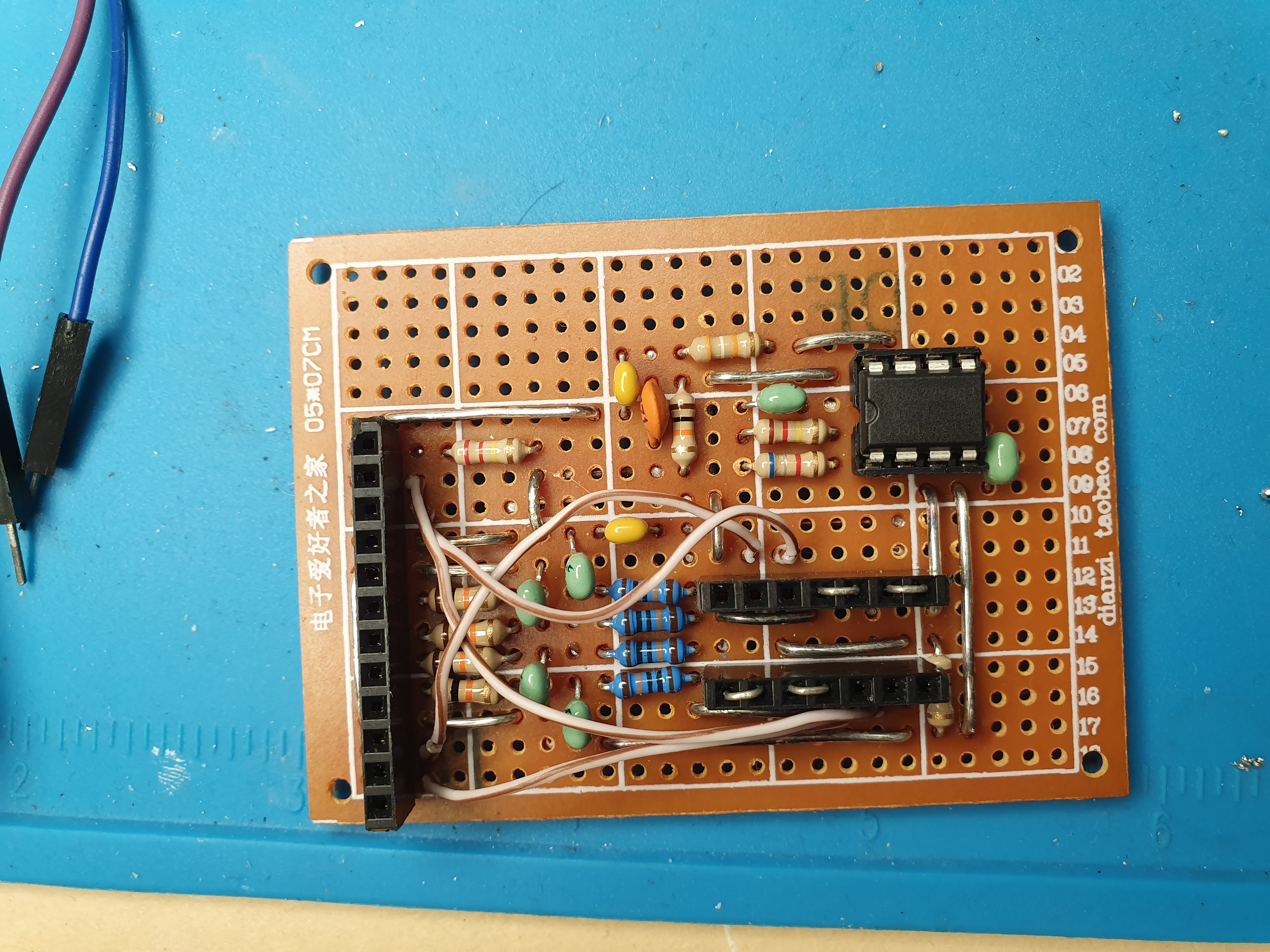
Audio filtering
As explained in the firmware description, the audio signal is modulated using a PWM signal. This PWM signal needs to be filtered in some way to remove the high frequency switching noise and get a good-looking audio signal.
The first prototype I developed was to research this. The final circuit I made is shown below.
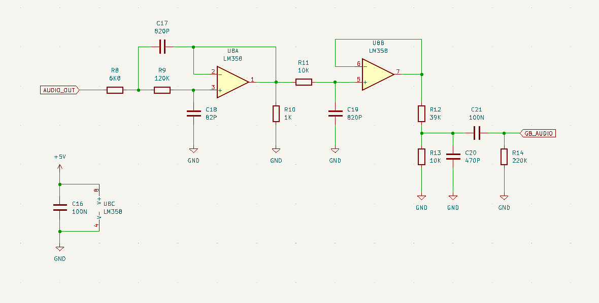
The PWM signal (coming in at AUDIO_OUT) is filtered by a 3rd order low-pass filter to extract the audio signal from the high-frequency PWM signal. The filter consists of a 2nd order Sallen-Key filter cascaded into a simple 1st order RC filter. Both filters have a corner frequency around 20kHz.
R10 connects the op-amp inverting input to ground. Otherwise, the inverting input is floating and the output clips, deforms and/or remains noisy. I have more about this phenomena written in my research report.
The output of the filter is passed to a voltage divider to attenuate the signal to proper CGB levels.
The audio signal is then capacitively coupled to the Gameboy's audio input. R14 pulls the biased GB_AUDIO line down for it to swing around 2.2V.
I also made pictures of the finished circuit below.
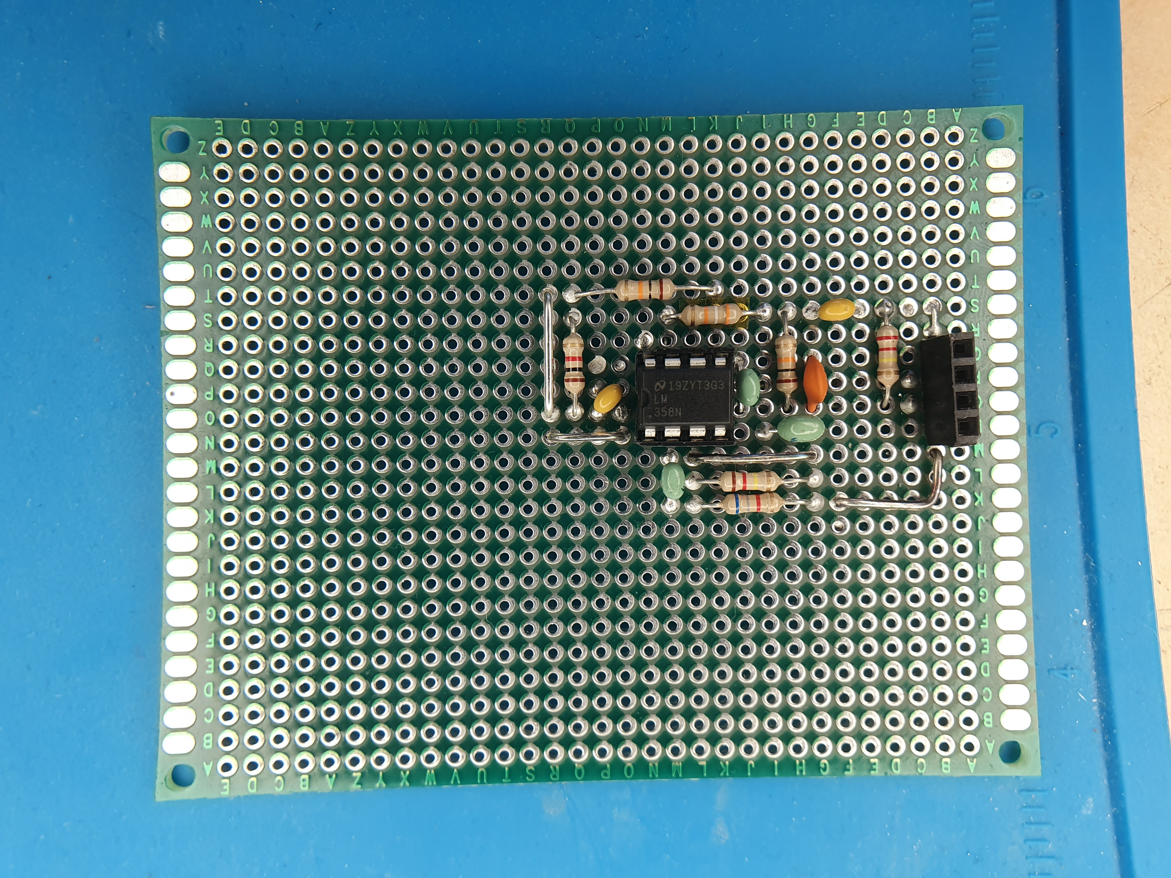
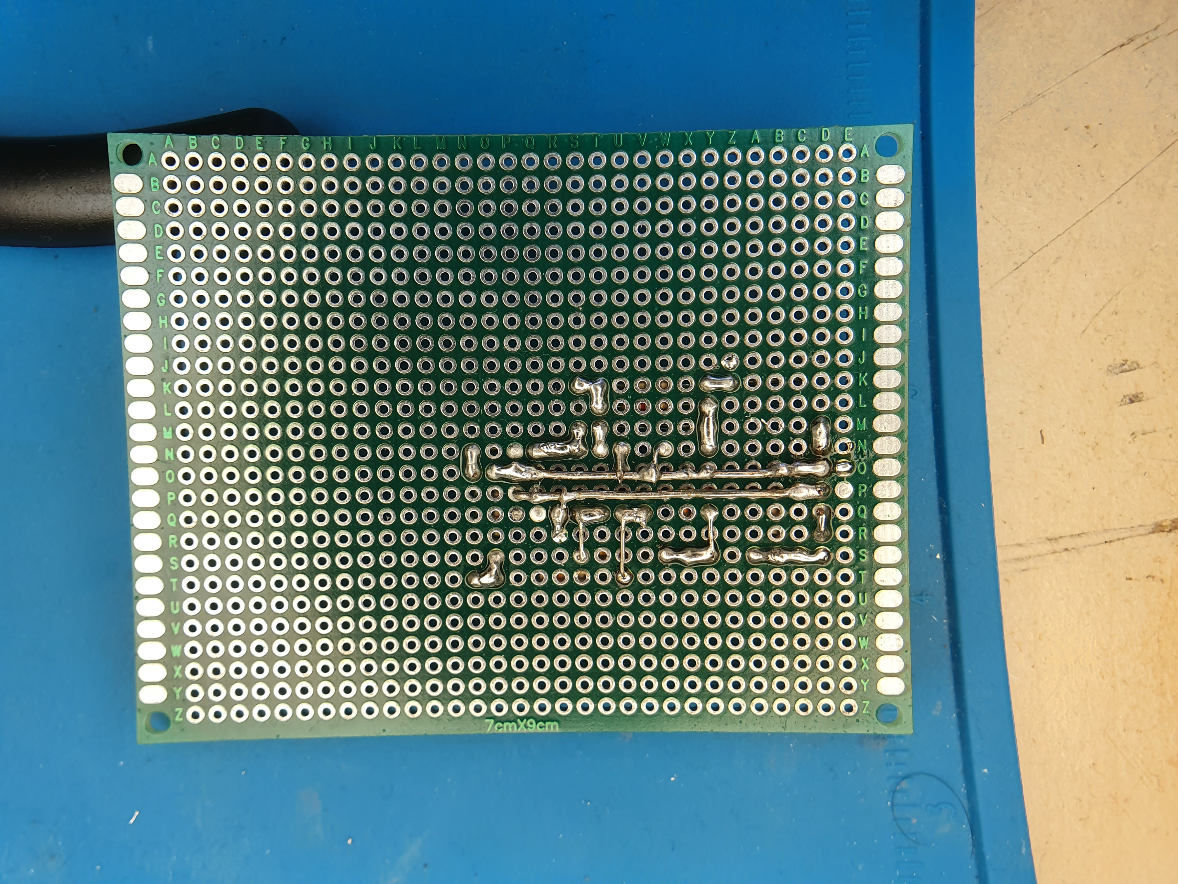
Audio mixing
After having researched volume control, I started research on mixing. I had 2 contenders: a summing amplifier and an averaging mixer. The summing amplifier just sums all input signals, while the averaging mixer calculated the average of all input signals. I liked the averaging filter better, so I went with that. I have its schematic shown below.
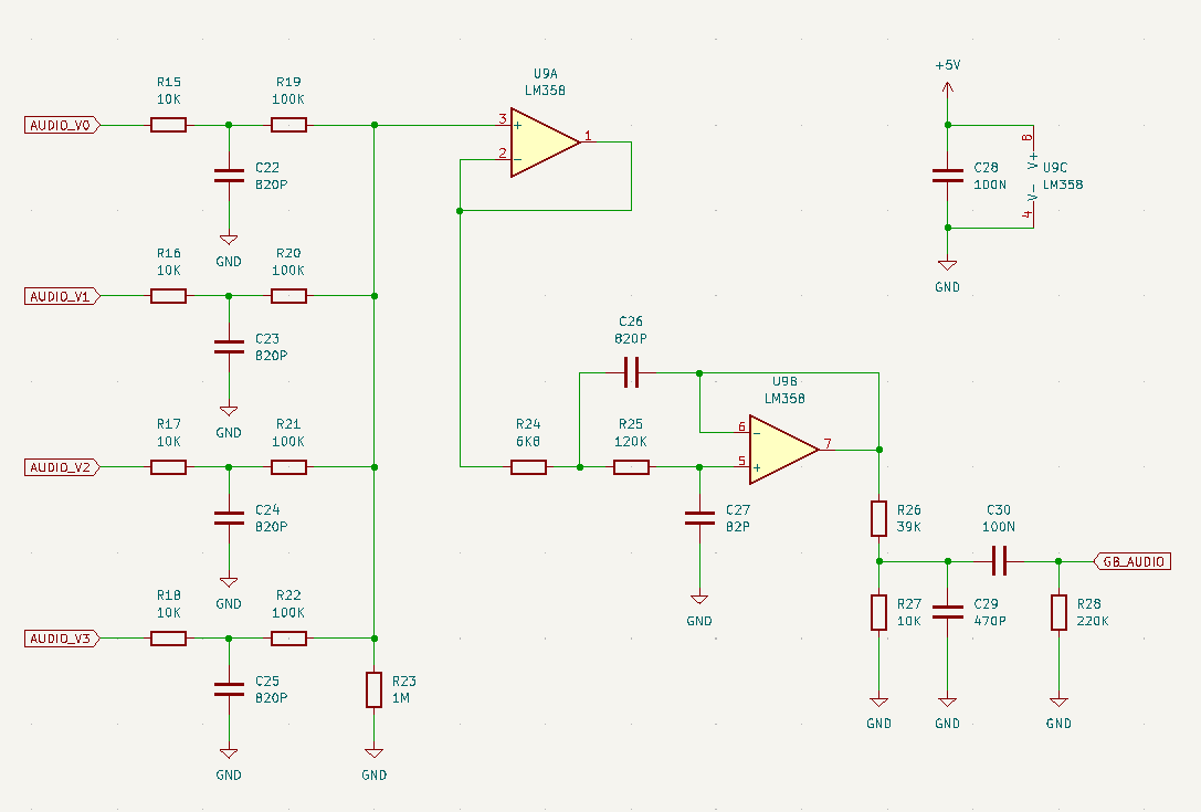
The audio signals come from AUDIO_V0 to AUDIO_V3 (the V standing for "voice", a term to refer to an audio channel).
The PWM signal is "pre-filtered" to remove part of the high frequency 200kHz wave. After this pre-filtering, the audio is mixed and buffered by the voltage follower.
Signal is then properly filtered by a 2nd order Sallen-Key filter. All filters have a corner frequency around 20kHz for cutting off frequencies above human hearing.
After the output of the 2nd opamp, it is just a copy-paste from the previous circuit.
I also added pictures of the finished prototype below.
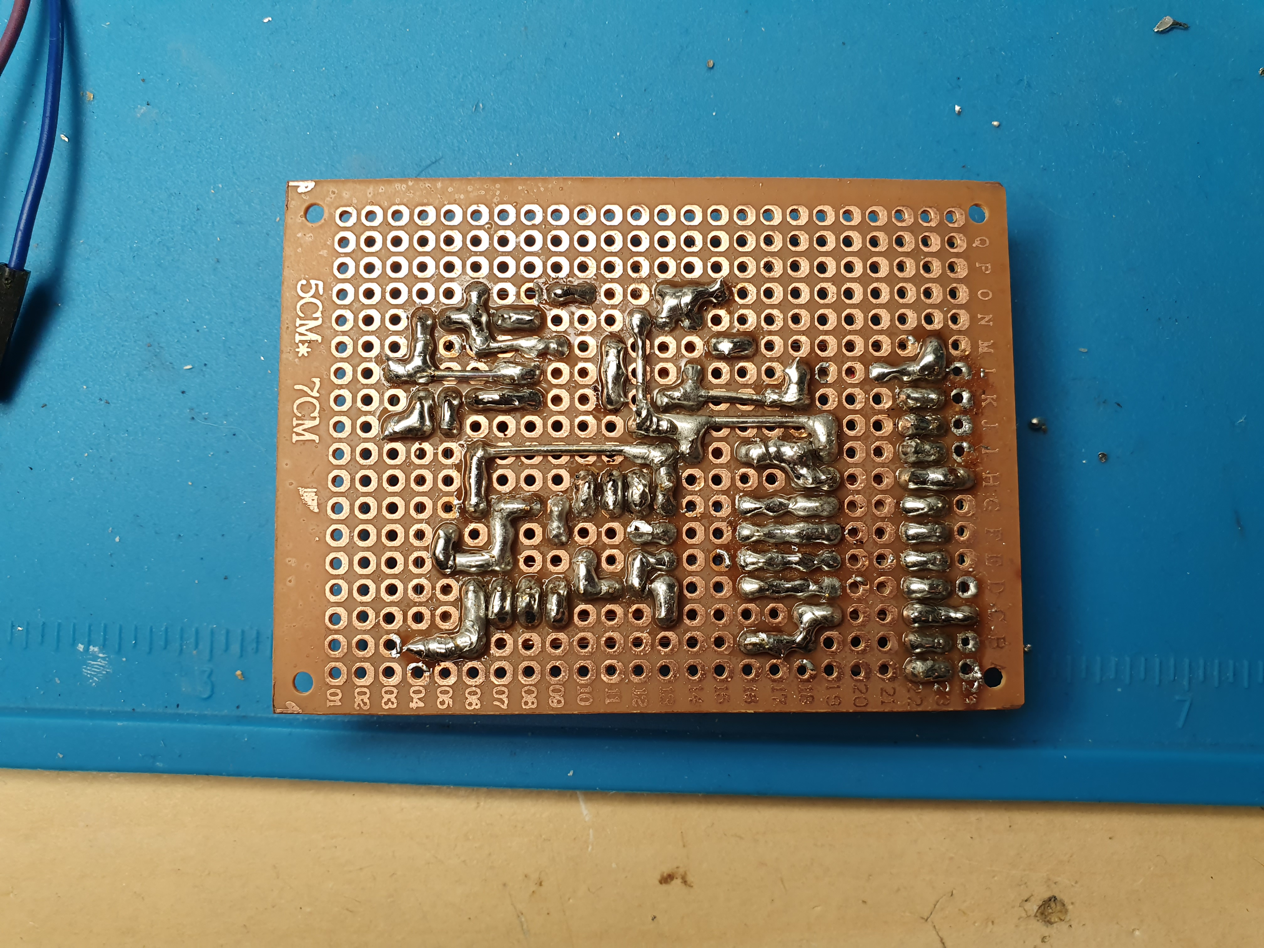
The 2x7 female pin headers are for an analogue switch IC. The only issue I saw with the averaging mixer was the fact that the output is always divided by the number of channels. In the case that only one channel is used, that channel’s output is always attenuated by a factor of ¼. If only one channel is used, of course I’d want that channel to use the entire volume range. This is solved easily by disconnecting the channel, which I planned to do with an analogue switch.
I do want to add a quick point: holy crap, it was annoying to solder this prototype... The astute may notice the perfboard having a different colour. Apparently this one doesn't have a soldermask, so solderpads close to each other were constantly bridging. Remember me to avoid them for delicate wiring...
I did wire everything correctly on the first time though, so I am quite glad. Well... I did wire the Vcc pin of the analogue switch incorrectly to 5V (should have been 3.3V), but that was an issue at the planning stage so that doesn't count.
Closing remarks
I've spent a crap load of time on this project this semester, and I am honestly a bit burned out. My excitement in researching the audio controller has long since died down, so since the semester ended and I am not forced to work on it anymore, I think I will leave it at that.
Ultimately, I am a software/firmware engineer at heart and prefer to work on those aspects, rather then hardware. The research is there of course, so I might continue in the future. Or heck, if an actual capable hardware engineer comes in and takes the project from me, I'd be the happiest little bean in the whole world.
Also, I think I am not just burned out from the audio part, but from the project in general. I haven't have fun working on it for a while, so I think I'll take a hiatus on the project. Don't expect any new updates for the time being.
I am also planning to remodel my bedroom during the summer, so that will be my new project for the summer. I also have a crap ton of other stuff to do, like finally fixing my sister's Nintendo Switch and 3DS. They have been partly disassembled in a corner of my room for a while now, might finally finish that.
For anyone interested in the nitty-gritty, I wrote extensively in my research report about my research. I tried to summarise my progress to the more interesting points in this post, but if you're somehow not bored already you can go read that.
But yeah, I think I'll take my leave. Goodbye for now and have a great summer (or winter if you live in the southern hemisphere).